In today’s datacenters, bandwidth demands are continually on the increase and to accommodate these bandwidth demands the speeds of the networks in the datacenter are also increasing. These network speeds increase with every evolution of network switches and the Silicon chips inside them. In the last 15 years, we have seen the main network speeds in datacenters increase from 1Gb/s to 10G, 40G, 25G, 100G and now the most advanced datacenters are deploying 400G networks. The fundamental building blocks of these datacenter networks are the network switches deployed. It is these switches that determine the speed at which the network runs.
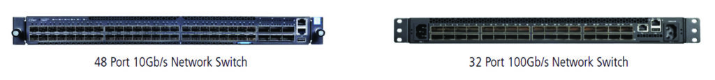
Network switches are generally categorised in terms of their ports and their speeds – as seen above, a 32 port 100Gb/s Switch is a network switch with 32 ports each of which is capable of running at 100Gb/s. In order for the switch to work, a transceiver is required to be plugged into the port on the switch in order to convert the electrical signals in the switch to signals which can be transmitted down a fiber optic cable or a copper cable. The reason for the separation of the transceiver and the switch is to allow the datacenter operator the flexibility (and cost efficiency) of selecting the most appropriate transceiver. For very short lengths (<90m @ 10G and <10m @ 40G), copper transceivers can be deployed as the cheapest option. For medium reach (<500m @10G and 150m @40G) MM VCSEL (Vertical Cavity Surface Emitting Lasers) transceivers are the most appropriate option. Above 500m @ 10G, 150m @ 40G and 100m @ 100G there are a variety of Single-mode (SM) transceivers designed for 500m reach, 2km reach, 10km reach and up to 30km reach with each variant increasing in cost.
As can be seen from the Network switches above, the port size for a 10G port is smaller than for a 100G (and a 40G) port. For 1G, 10G and 25G the form factor (shape) of the transceiver is a Small Form-factor Pluggable (SFP). For 40G and 100G, the form factor changes to a Quad Small Form-factor Pluggable (QSFP) with the Quad referring to a multiple of four – a 40G transceiver combines four lanes of 10Gb/s to achieve the 40Gb/s speed and a 100G combines four lanes of 25Gb/s.
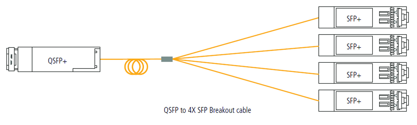
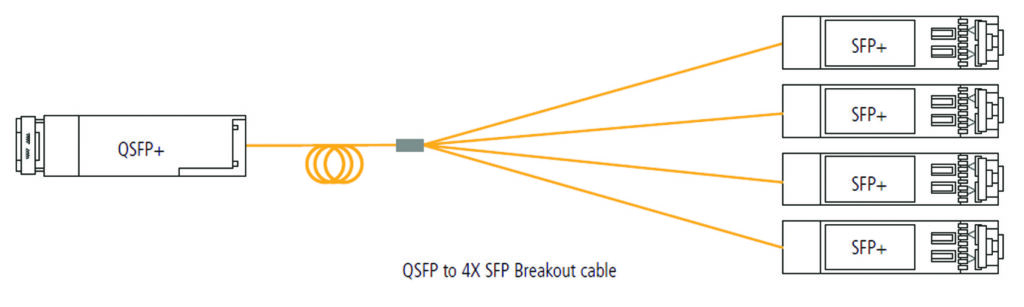
This four lane aggregation has the added advantage of allowing four devices to connect at the lower lane speed to one switch port at the higher aggregate speed – ie four servers running at 25G each can connect to one switch port running at 100G. Once the datacenter operator has installed their switch and selected the transceivers for the desired reach, the network is typically connected through the installed structured cabling system, using fiber (or copper) patchcords to connect the transceivers to the system.
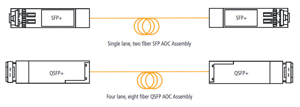
However, in some instances, where network switches and / or servers are located relatively close to each other, instead of using two transceivers and fiber cabling, an Active Optical Cable (AOC) can be deployed. An AOC can be thought of as a simple LC or MPO patchcord with the LC or MPO connectors being replaced by a transceiver “connector”. They are gaining popularity as they are significantly lower cost than two transceivers and a patchcord and they eliminate any issues relating to connector end face contamination as the optical connection is replaced with an electrical one. They are lower cost due to their use of highly efficient Multimode VCSEL optics inside the transceivers.
They are commonly used in several locations within the datacenter. The first is in server cabinets, where up to 40 servers all connect up to a Top of Rack Ethernet switch. Each server will have one or two Ethernet connections up to the switch and these can be patched using AOC cables. The second most significant use of AOCs in the datacenter is in the main networking area which can be in the Spine, Leaf or Core switching area. In today’s networks, in these areas, there are large numbers of discreet switches which are all interconnected to create a large Fabric switch – up to half of the ports in the switches are used for these interconnects. These interconnects are typically now fulfilled using AOCs. In some datacenters, these large fabric switches can occupy multiple cabinets and even up to a whole row in the datacenter, the AOCs can be used even in these longer reach applications with their theoretical maximum reach being 100m.
| AOC | Aggregate Speed | Lane Speed | Lanes | Fibers | Reach |
|---|---|---|---|---|---|
| 10G SFP+ – SFP+ | 10Gb/S | 10Gb/s | 1 | 2 | 100m |
| 25G SFP28 – SFP28 | 25Gb/S | 25Gb/S | 1 | 2 | 70m |
| 40G QSFP+ – QSFP+ | 40Gb/S | 10Gb/s | 4 | 8 | 100m |
| 40G QSFP+ – 4X 10G SFP+ | 40Gb/S | 10Gb/s | 4 | 8 | 100m |
| 100G QSFP28 – QSFP28 | 100Gb/S | 25Gb/s | 4 | 8 | 70m |
| 100G QSF28 – 4X 25G SFP28 | 100Gb/S | 25Gb/s | 4 | 8 | 70m |
| 400G OSFP – OSFP PAM4 | 400Gb/S | 25Gb/s | 8 | 16 | 30m |
All AOCs typically share the same MM VCSEL optics with the VCSELs either transmitting at 10Gb/s or 25Gb/s. 10Gb/s AOCs have one transmit and receive pair inside the transceiver and deploys duplex MM fiber while a 40Gb/s AOC has four transmit and receive pairs and deploys 8 fiber MM cable. The same duplex and 8 fiber arrangement is deployed in the 25Gb/s and 100Gb/s AOCs with the 100Gb/s having four lanes of 25Gb/s.
At 400Gb/s, things are a little more complex with eight lanes of 25Gb/s being deployed to give 200Gb/s which is encoded with PAM-4 coding which doubles the line speed, increasing the effective speed from 200Gb/s to 400Gb/s. The form factor of the changes to a slightly larger OSFP (Octal Small Form-factor Pluggable) and the fiber count in the cable increases to 16 MM fibers. Due to the complexity of the coding and the lane speed, the distance capability also drops to a maximum of 30m.
